
Physical Computing: Week 10 - Controlling DC & Stepper Motors with a H-Bridge
Summary
Motion and mobility, I find, are two aspects of physical computing that encourage more interactivity in your project and I am excited to see how I can use it in the future! For this week’s lab, I worked with a DC and stepper motor and learned how they can be useful in creating fun projects. Although they were fun to get accustomed to, they also caused me multiple headaches during the circuit setup process. All in all, this process was a great experience so let’s take a look.
Controlling DC Motor with a H-Bridge
Setup:

This setup is the final product after multiple tries at a working circuit. At first, I tried to the use the mentioned setup without the additional power supply and jack. The DC motor I used for this lab was a 3-6 voltage motor and is compatible with the USB power supply of the Arduino. However, I did not have a few things set up properly which derailed my progress for a while. I realized through additonal helping hands that the 5 voltage chips on the back of the Arduino were sodder together which inevitably did not drive enough power to the motor connected to the H-Bridge. I also did not have the VM (motor voltage supply input) connected to the power bus. Lastly, I had initially connected the capacitor to the power and ground bus but understood, after the fact, that the capacitor is only needed to smooth out possible voltage dips when the motor turns on. After correcting these mistakes, I was able to have a proper setup for a working motor.
Code & Demo:
1
2
3
4
const int switchPin = 2;    // switch input
const int motor1Pin = 3;    // Motor driver leg 1 (pin 3, AIN1)
const int motor2Pin = 4;    // Motor driver leg 2 (pin 4, AIN2)
const int pwmPin = 9;       // Motor driver PWM pin
This block of code sets up constants for the switch pin, the two motor driver pins, and the PWM enable pin of the motor driver.
1
2
3
4
5
6
7
8
9
10
11
12
void setup() {
    // set the switch as an input:
    pinMode(switchPin, INPUT);

    // set all the other pins you're using as outputs:
    pinMode(motor1Pin, OUTPUT);
    pinMode(motor2Pin, OUTPUT);
    pinMode(pwmPin, OUTPUT);

    // set PWM enable pin high so that motor can turn on:
    digitalWrite(pwmPin, HIGH);
}
This block of code sets all the pins for the motor driver as outputs, and the pin for the switch as an input. Then sets the PWM enable pin high so the H-bridge can turn the motor on.
1
2
3
4
5
6
7
8
9
10
11
12
void loop() {
    // if the switch is high, motor will turn on one direction:
    if (digitalRead(switchPin) == HIGH) {
      digitalWrite(motor1Pin, LOW);   // set leg 1 of the motor driver low
      digitalWrite(motor2Pin, HIGH);  // set leg 2 of the motor driver high
    }
    // if the switch is low, motor will turn in the other direction:
    else {
      digitalWrite(motor1Pin, HIGH);  // set leg 1 of the motor driver high
      digitalWrite(motor2Pin, LOW);   // set leg 2 of the motor driver low
    }
}
This block of code reads the switch. If it’s high, it turns the motor one way by taking one motor driver pin high and the other low. If the switch is low, it reverses the direction by reversing the states of the two pins.
Here is a video of this being demonstrated:
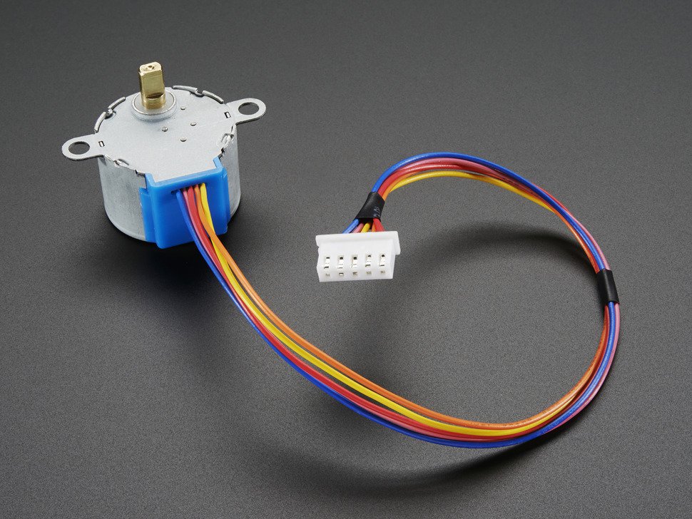
Controlling Stepper Motor with a H-Bridge
Setup:

This setup was not fair at all, to say the least. The lab primarily showed schematics for a separate H-Bridge circuit connected to different Arduino versions that did not include the Nano. I tried to follow the schematics with similar connections to the H-Bridge circuit that I used but the stepper motor was unsuccessful in turning on. Let’s get into the code to see what the stepper motor was supposed to do.
Code & Demo:
1
2
3
4
5
6
7
8
9
10
11
12
13
14
15
16
17
18
19
20
21
22
23
#include "Stepper.h"

const int stepsPerRevolution = 512;  // change this to fit the number of steps per revolution
                                     // for your motor

// initialize the stepper library on pins 8 through 11:
Stepper myStepper(stepsPerRevolution, 8,9,10,11);

int stepCount = 0;         // number of steps the motor has taken

void setup() {
  // initialize the serial port:
  Serial.begin(9600);
}

void loop() {
  // step one step:
  myStepper.step(1);
  Serial.print("steps:" );
  Serial.println(stepCount);
  stepCount++;
  delay(500);
}
This block of code runs the stepper motor through the H-bridge using the Stepper library. It runs the stepper one step at a time, to see that all the wires are connected correctly. If they are, the stepper will step one step forward at a time, every half second.
1
2
3
4
5
6
7
8
9
10
11
12
13
14
15
16
17
18
19
20
21
22
23
24
25
26
#include "Stepper.h"

const int stepsPerRevolution = 512;  // change this to fit the number of steps per revolution
                                     // for your motor

// initialize the stepper library on pins 8 through 11:
Stepper myStepper(stepsPerRevolution, 8,9,10,11);

void setup() {
  // set the speed at 60 rpm:
  myStepper.setSpeed(10);
  // initialize the serial port:
  Serial.begin(9600);
}

void loop() {
  // step one revolution  in one direction:
   Serial.println("clockwise");
  myStepper.step(stepsPerRevolution);
  delay(500);

   // step one revolution in the other direction:
  Serial.println("counterclockwise");
  myStepper.step(-stepsPerRevolution);
  delay(500);
}
This block of code makes the stepper move one whole revolution at a time.
Assuming that my setup is faulty in its circuit connections, I was not able to capture a video of a working stepper motor but I hope to troubleshoot this in class with answered questions
Questions & Takeaways
- Why are the schematics for the Arduino MKR different from the Nano?
- Why do we use two ground instead of one for the motor driver?